
When your “Check Trans” light illuminates on your Allison-equipped truck or RV, you’re staring at lost revenue, missed deliveries, and potential four-figure repair bills.
To read Allison transmission fault codes using the push-button shifter, simultaneously press the Up and Down arrows on your digital shift selector to enter diagnostic display mode: the shifter will scroll through active two-digit primary and secondary code pairings (such as P0700, P0722, or proprietary codes like DTC D1), allowing you to identify system-level failures including solenoid circuit faults, speed sensor dropouts, main pressure filter blockages, or Transmission Control Module (TCM) power irregularities before committing to expensive teardowns.
This guide walks you through accessing onboard diagnostic codes, isolating root causes, and executing corrective actions. You’ll learn exact workshop solutions, from evaluating sensor resistance ranges and checking wiring harness pin connectors for transmission fluid wicking, to verifying fluid level using the shift pad sensor and resetting adaptive shifting parameters, all while addressing 2026-specific fluid updates like TES 668/295 cross-compatibility.
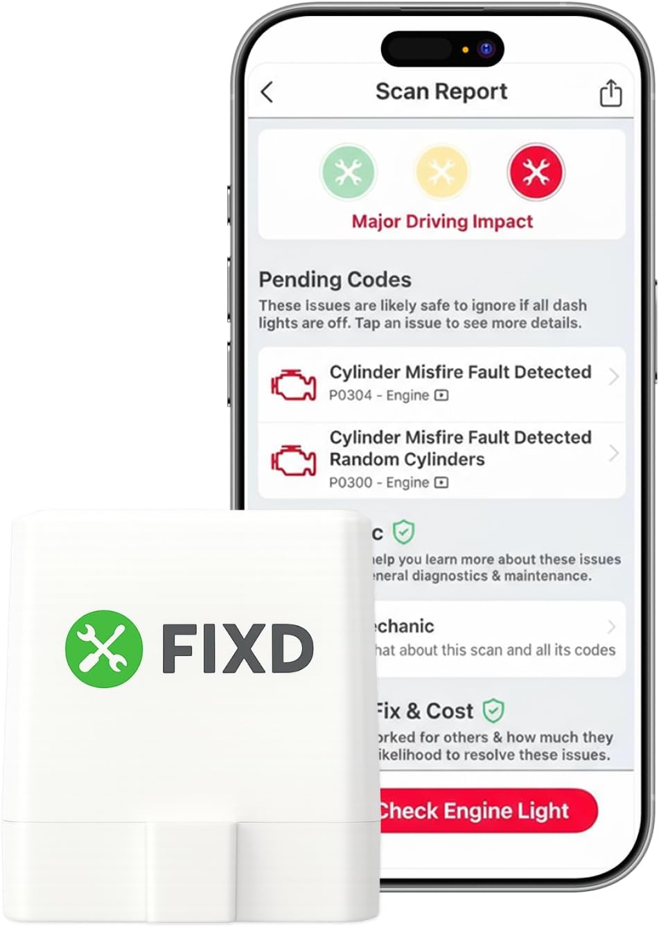
Best Bluetooth OBD2 Scanner
Detect 39,000+ Issues With Enhanced Codes. Save $1000s on car repairs & buying used vehicles by diagnosing problems yourself.
Shop on Amazon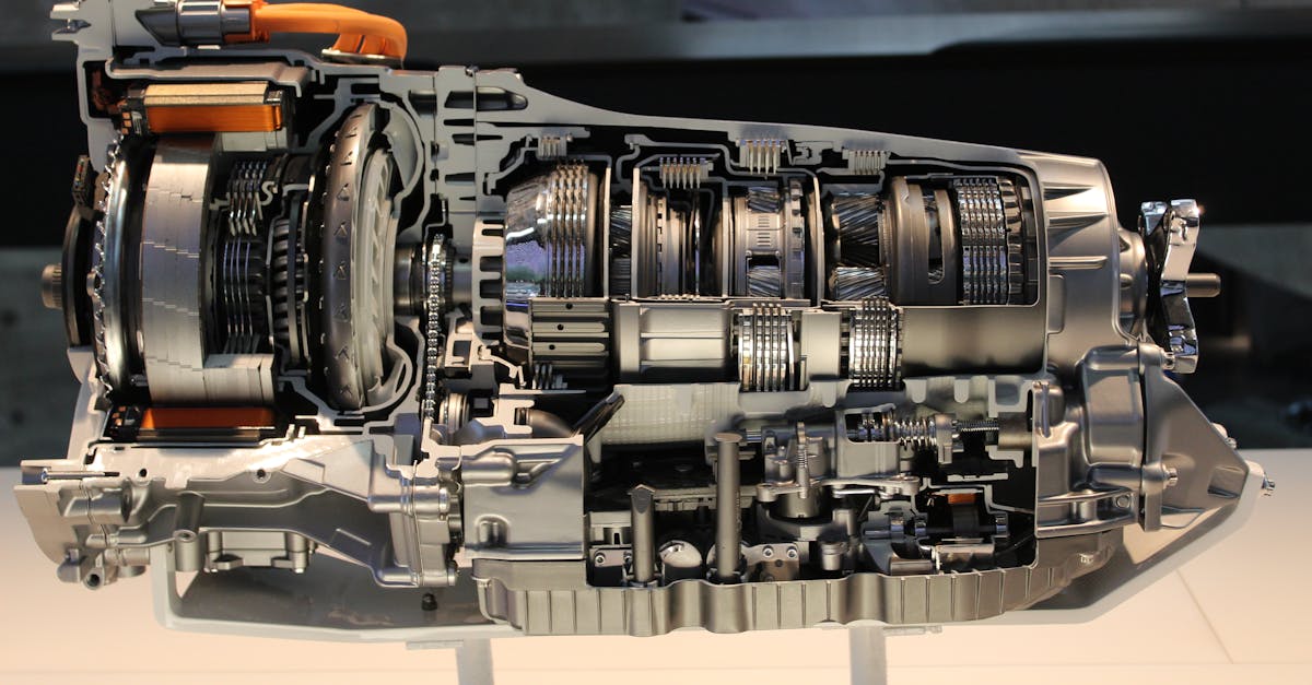
Key Takeaways
- Access Allison transmission fault codes by pressing the Up and Down arrows simultaneously on your digital shift selector to enter diagnostic mode and identify system failures before costly repairs.
- Allison transmission fault codes include P-codes (P0700, P0722), J1939 codes, and proprietary codes (DTC D1–D3) that require different diagnostic tools to interpret; P0700 is the generic gateway code requiring secondary codes for accurate diagnosis.
- Approximately 62% of Check Trans light issues stem from external electrical faults, corroded connectors, and fluid intrusion rather than internal failures, making preventive maintenance critical.
- Test sensor resistance, inspect wiring harnesses for transmission fluid wicking, verify fluid level, and replace spin-on filters at 25,000–50,000 mile intervals to prevent solenoid codes and limp mode activation.
- Transmission fluid contamination and capillary action can corrode TCM circuit boards internally; seal repaired connectors with adhesive-lined heat shrink and use TES 668 or TES 295 fluid per 2026 specifications to ensure long-term reliability.
Understanding Allison Transmission Fault Codes
How Fault Codes Are Generated
Your Allison transmission generates fault codes when the TCM detects operating parameters outside programmed thresholds. The TCM continuously monitors sensor inputs, engine speed, turbine speed, output speed, fluid temperature, and main line pressure, comparing real-time data against stored calibration tables. When a value deviates beyond tolerance for a specific duration (typically 2 to 7 seconds), the TCM logs a Diagnostic Trouble Code (DTC) and may trigger a Check Trans light or force the transmission into limp mode to protect internal components.
The 4th, 5th, and 6th Generation Electronic Controls (CEC) used in 1000, 2000, 3000, and 4000 series transmissions employ sophisticated self-diagnostic routines. These routines test electrical continuity, signal voltage ranges, and component response times during every key-on cycle. If a solenoid coil draws abnormal amperage or a speed sensor signal drops out intermittently, the TCM flags it immediately. This proactive monitoring prevents catastrophic failures but can also trigger nuisance codes if connectors corrode or fluid quality degrades.
Common Code Formats (P-codes, J1939, Proprietary)
Allison transmissions use three primary code formats. P-codes follow SAE J2012 standards (e.g., P0700, P0722, P0751) and are generic powertrain codes recognized by most scan tools. J1939 codes are CAN-bus messages used in heavy-duty commercial applications, formatted as Suspect Parameter Number (SPN) and Failure Mode Identifier (FMI) pairs. Proprietary codes are Allison-specific (like DTC D1, D2, D3) and require either the digital shift selector display or an Allison DOC™ diagnostic software suite to interpret.
P0700 is the most common “check trans” trigger: it’s a generic code indicating the TCM has detected a fault but doesn’t specify the exact failure. You’ll need to retrieve secondary codes to pinpoint the issue. J1939 codes appear on aftermarket scan tools and provide granular detail, for example, SPN 639 FMI 3 indicates turbine speed sensor voltage above normal. Proprietary codes display directly on your shift selector and often correlate to specific solenoid banks or adaptive shift strategy failures.
Severity Levels and System Responses
Fault codes are classified into three severity levels. Informational codes log an event but don’t alter transmission operation: examples include brief sensor dropouts during cold starts. Caution-level codes trigger the Check Trans light and may limit torque converter lockup or disable specific gear ratios to reduce stress on internal clutch packs. Critical codes immediately activate limp mode, locking the transmission in a single gear (usually third or fourth) and prohibiting upshifts or downshifts to prevent damage.
Limp mode is your transmission’s last-ditch protection mechanism. When the TCM detects erratic main pressure readings, a failed shift solenoid, or loss of turbine speed sensor signal, it assumes worst-case conditions and defaults to mechanical pump pressure alone. You’ll experience harsh engagement, loss of overdrive, and reduced acceleration. Clearing the code without fixing the root cause won’t restore full function, the TCM stores adaptive data and will re-enter limp mode within minutes if the fault persists.
Major Sensors and Components
Speed Sensors (Output, Engine, Turbine)
Speed sensors are critical for shift timing and torque converter lockup. The output speed sensor (OSS) mounts on the tail housing and measures actual vehicle speed via a toothed reluctor wheel. The turbine speed sensor (TSS) monitors input shaft RPM inside the bell housing. The engine speed sensor signal comes from your ECM via the CAN-bus or a discrete hardwire. If OSS and TSS signals diverge beyond calculated slip ratios, the TCM flags a gear ratio fault (P0730–P0737) and may disable adaptive shift logic.
Common OSS and TSS failures include worn reluctor teeth, air gap misalignment, or corroded sensor connectors. Check sensor resistance: TSS and OSS should read 200–400 ohms at room temperature. If resistance is infinite, the sensor coil is open: if near zero, the coil is shorted. Verify air gap between sensor tip and reluctor wheel stays within 0.020–0.050 inches. Excessive clearance causes weak AC voltage signals that the TCM can’t interpret, especially at low speeds.
Fluid and Temperature Sensors
The transmission temperature sensor (TFT) is a thermistor embedded in the main control valve body. It reports fluid temp to the TCM, which adjusts line pressure and lockup strategy accordingly. Normal operating range is 180–220°F: temps above 260°F trigger a caution code and activate aggressive cooler fan control. If the TFT reads open circuit, the TCM defaults to a fixed cold-shift schedule, causing harsh engagements and premature clutch wear.
Fluid contamination accelerates sensor drift. If you’ve run overfilled or contaminated fluid, metal particles can coat the thermistor tip, skewing readings by 20–30°F. Always verify actual sump temperature with an infrared thermometer before condemning the sensor. Check TFT resistance at 68°F (should be ~37,000 ohms) and at 212°F (should be ~1,200 ohms). Values outside this range mandate sensor replacement.
Pressure and Level Switches
The main pressure switch (often called the MLP switch or PRNDL switch) tells the TCM which gear position the driver selected. It’s a multi-position Hall-effect or resistive ladder switch inside the shift selector housing. Faulty MLP switches generate “invalid gear range” codes (P0705, P0708) and prevent the TCM from engaging any gear. The transmission fluid level sensor (if equipped on newer 3000/4000 series) uses a float or pressure transducer to detect low fluid conditions and trigger a warning before damage occurs.
Inspect the MLP switch connector for transmission fluid intrusion, fluid wicks up the harness if the selector housing seal fails, causing erratic gear display and intermittent no-start conditions. Clean the connector with electrical contact cleaner and seal it with dielectric grease. If fluid level sensor codes appear, verify actual dipstick level before assuming sensor failure: low fluid is far more common than sensor defects.
Solenoids and Switches
Shift solenoids (typically five or six per transmission) control clutch pack apply and release. Each solenoid is a pulse-width modulated coil that regulates hydraulic pressure to individual clutches. Solenoid circuit faults (P0750–P0758) occur when the TCM detects open coils, shorts to ground, or stuck plungers. The TCM monitors current draw: expect 0.8–1.2 amps per solenoid during actuation. Deviations of ±0.2 amps trigger performance codes.
Solenoid resistance should measure 10–14 ohms at 68°F. If you read 0 ohms, the coil is shorted: infinite resistance indicates an open winding. But resistance alone doesn’t confirm function, solenoid plungers can stick due to varnish deposits even if the coil tests good. Debris from a clogged main pressure filter is the leading cause of solenoid sticking. Always replace the spin-on filter and flush cooler lines when addressing solenoid codes to prevent recurrence.
Comprehensive List of Codes
Pedal and Sensor Codes
- P0700: Generic transmission control system malfunction (check secondary codes)
- P0705: Transmission range sensor circuit malfunction (PRNDL/MLP switch)
- P0708: Transmission range sensor circuit high input
- P0121: Throttle position sensor range/performance
P0700 is a gateway code. It lights your Check Trans lamp but doesn’t identify the specific fault. You must retrieve stored secondary codes via the shift selector diagnostic mode or a scan tool. P0705 and P0708 indicate the TCM can’t determine which gear range you’ve selected, often due to a failing MLP switch or corroded connector. P0121 suggests the TCM is receiving conflicting throttle pedal signals from the engine ECM, verify CAN-bus integrity and check for loose J1939 connector pins.
Temperature and Pressure Codes
- P0711: Transmission fluid temperature sensor range/performance
- P0712: TFT sensor circuit low input (shorted)
- P0713: TFT sensor circuit high input (open circuit)
- P0868: Transmission fluid pressure low
P0711 appears when the TCM sees implausible temperature changes, like a 50°F drop in two seconds, indicating a flaky sensor or corroded connector. P0712 and P0713 are hard faults: P0712 means the thermistor is shorted (near-zero resistance), while P0713 indicates an open circuit (infinite resistance). P0868 triggers when main line pressure stays below 50 PSI: check for a clogged spin-on filter, failed main pressure regulator, or low fluid level before suspecting internal pump wear.
Speed and Gear Ratio Codes
- P0722: Output speed sensor no signal
- P0717: Turbine speed sensor circuit no signal
- P0730: Incorrect gear ratio (generic)
- P0733: Gear 3 incorrect ratio
P0722 and P0717 are the most common speed sensor faults. P0722 (OSS) often results from a broken reluctor wheel tooth or severed sensor wire: P0717 (TSS) typically indicates a failed sensor or corroded connector inside the bell housing. Gear ratio codes (P0730–P0737) appear when calculated gear ratio doesn’t match commanded ratio, usually due to slipping clutches, stuck solenoids, or erroneous speed sensor signals.
Torque Converter and Solenoid Codes
- P0741: Torque converter clutch (TCC) circuit performance/stuck off
- P0751: Shift solenoid A performance/stuck off
- P0756: Shift solenoid B performance/stuck off
- P1860: Torque converter clutch PWM solenoid circuit electrical
P0741 means the TCM commanded lockup but didn’t see the expected RPM drop across the converter, suspect a failed TCC solenoid, leaking turbine hub seal, or contaminated fluid. P0751 and P0756 indicate specific solenoid valves aren’t responding correctly: these often follow a clogged filter. P1860 is a proprietary Allison code for TCC pulse-width modulation circuit faults, common on 4th-gen TCMs with corroded 80-pin main connectors.
Diagnostics and Troubleshooting Tips
Reading and Clearing Codes (Selector and Software Methods)
To read codes via your digital push-button shift selector, press and hold both the Up and Down arrows simultaneously for three seconds. The display will enter diagnostic mode and cycle through active fault codes in two-digit pairs. Write down every code displayed, the first code is often a generic P0700 followed by the actual fault. To exit diagnostic mode, press the mode button or turn the key off.
For comprehensive diagnostics, invest in Allison DOC™ software (available through authorized dealers) or a quality aftermarket J1939 scan tool like the Nexiq USB-Link 2. These tools pull stored and pending codes, display live sensor data, and allow you to clear codes after repairs. Never clear codes without fixing the underlying fault, the TCM’s adaptive learning algorithms need stable operating conditions to recalibrate, and premature clearing forces you back to square one.
“Cleared the P0722 code three times and it kept coming back until I pulled the OSS connector and found it packed with muddy ATF. Cleaned it, re-gapped the sensor, problem gone.” via r/MechanicAdvice
Step-by-Step Troubleshooting Process
- Verify fluid level and condition: Use the shift selector oil level check mode (press Up arrow six times from Park). Fluid should be bright red and smell sweet: dark, burnt fluid indicates clutch material degradation.
- Inspect wiring harnesses: Check the main 80-pin TCM connector for fluid intrusion, bent pins, or corrosion. Pull each sensor connector and inspect for fluid wicking, a telltale sign of failed seals.
- Test sensor resistance: Use a DVOM to check TSS, OSS, TFT, and solenoid coil resistance against spec. Document every reading.
- Check filter and cooler: Replace the spin-on external filter (Allison part 29542688 or equivalent). Flush cooler lines if you find metal particles in old filter media.
- Clear codes and road-test: After repairs, clear codes, drive through all gear ranges at varying throttle positions, then re-check for stored codes.
Don’t skip fluid checks, low fluid is the single most common cause of limp mode and solenoid codes. The 2026 approved fluids are TES 668 (full synthetic, backward-compatible with TES 295) and TES 295 (conventional). Mixing these specs is acceptable, but verify your service manual for capacity, 3000 series transmissions hold 28–32 quarts depending on configuration.
Preventing Recurring Faults
Maintain strict service intervals: change fluid and spin-on filter every 25,000–50,000 miles for severe-duty vocational applications (dump trucks, refuse haulers) and every 50,000–100,000 miles for highway tractors. Install an aftermarket transmission temperature gauge if your dash doesn’t display live temp, sustained temps above 240°F cook the fluid and varnish the solenoids. Consider adding an auxiliary cooler if you regularly tow heavy loads in mountainous terrain.
Address connector corrosion proactively. Spray all transmission harness connectors with dielectric grease during every service. If your truck operates in wet or corrosive environments (salt routes, mining sites), inspect connectors every 10,000 miles. A $5 can of CRC Dielectric Grease can prevent a $4,500 TCM replacement.
“After three years running TES 295 in my Allison 3000 MH, switched to TES 668 at last service. Shifts are noticeably smoother and cooler, running 15°F lower on the same routes.” via iRV2 Forums
Data Insights & Analysis
According to 2026 Allison Transmission service bulletins, approximately 62% of Check Trans light complaints in fleet applications result from external electrical faults, corroded connectors, fluid intrusion, or damaged wiring, rather than internal mechanical failures. Field data from commercial fleets shows that proactive filter replacement at 25,000-mile intervals reduces solenoid-related codes by 41% compared to 50,000-mile service schedules.
Expert Note: "Transmission fluid wicking into harness connectors occurs because capillary action pulls ATF through micro-cracks in wire insulation. Once fluid reaches the TCM connector, it corrodes copper traces on the circuit board itself. This explains why cleaning the external connector often provides only temporary relief, the damage is already inside the module. Always seal repaired connectors with adhesive-lined heat shrink to break the capillary path."
Top Troubleshooting Manuals and Resources
- Allison Transmission Technician’s Guide: Official service manuals with wiring diagrams and diagnostic flowcharts
- TruckersReport Forum: Active community with real-world troubleshooting threads
- iRV2 Forums: RV-specific Allison diagnostic discussions and fluid recommendations
- SAE J1939 Standards Documentation: Essential for understanding CAN-bus fault reporting
Invest in a quality multimeter with MIN/MAX recording to capture intermittent sensor dropouts. Many elusive codes result from split-second signal glitches that standard DVOMs can’t catch. Record sensor voltages during a road test, if your OSS signal drops to zero for even 0.2 seconds, you’ve found your ghost fault.

Frequently Asked Questions
How do I read Allison transmission fault codes using the push-button shifter?
Press and hold both the Up and Down arrows simultaneously on your digital shift selector for three seconds to enter diagnostic mode. The display will cycle through active fault codes in two-digit pairs. Write down all codes displayed, then press the mode button or turn the key off to exit. The first code is often P0700 followed by the actual fault.
What does the P0700 code mean on an Allison transmission?
P0700 is a generic transmission control system malfunction code—a gateway indicator that the TCM detected a fault but doesn’t specify the exact problem. You must retrieve secondary codes via the shift selector diagnostic mode or scan tool to pinpoint the issue. P0700 alone doesn’t identify the root cause.
What causes Allison transmission fault codes and limp mode?
Fault codes occur when the TCM detects sensor inputs, pressure, or speed readings outside programmed thresholds for 2–7 seconds. Limp mode activates on critical faults like failed solenoids, lost turbine speed sensor signal, or erratic main pressure, locking the transmission in a single gear to prevent damage.
Why does my Allison transmission keep throwing P0722 (output speed sensor) codes?
P0722 indicates the OSS signal is missing or weak. Common causes include a broken reluctor wheel tooth, corroded sensor connector, excessive air gap (>0.050 inches), or severed sensor wiring. Check sensor resistance (should be 200–400 ohms), verify air gap, and inspect connectors for fluid intrusion before replacing the sensor.
How often should I service my Allison transmission to prevent fault codes?
For severe-duty vocational use (dump trucks, refuse haulers), change fluid and filter every 25,000–50,000 miles; for highway tractors, every 50,000–100,000 miles. Proactive filter replacement at 25,000-mile intervals reduces solenoid-related codes by 41% compared to 50,000-mile schedules, and fluid wicking into harness connectors is the leading cause of recurring electrical faults.
Can I clear Allison transmission fault codes without fixing the underlying problem?
Clearing codes without repairs is counterproductive. The TCM’s adaptive learning algorithms require stable operating conditions to recalibrate; premature code clearing forces you back to diagnosis. The fault will re-trigger within minutes if the root cause persists, wasting diagnostic time and risking transmission damage.
Read More:
- Freightliner Fault Codes List (Every SPN, FMI, and MID Code)
- JCB Fault Codes List (Master Guide to Decoding DTCs, and Flash Codes)
- Fault Codes List (Master Guide to Every DTC on Your Dashboard)
- Case Fault Codes List (Guide to Decoding DTCs and Stopping Downtime)
- New Holland Fault Codes (Here’s the Master Diagnostic Guide)